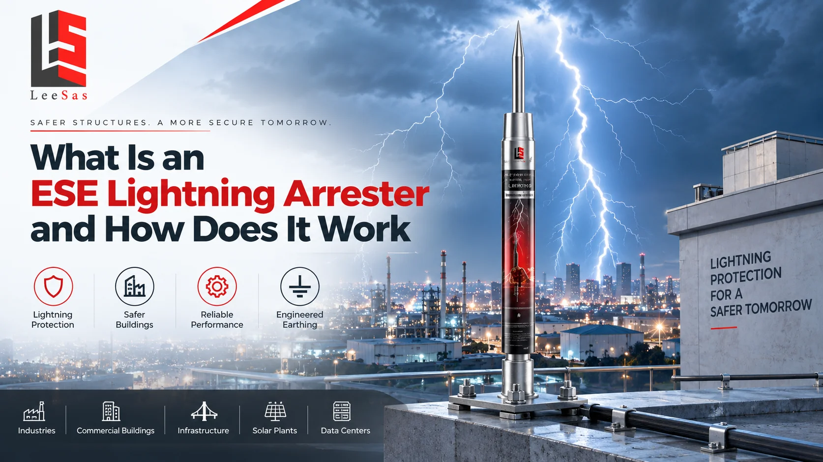
An ESE lightning arrester is an air terminal installed at a high point of a structure as part of an external lightning protection system. ESE stands for early streamer emission. Under the ESE design concept, the terminal is intended to initiate an upward connecting leader earlier than a reference conventional rod when the electric field around a developing lightning discharge becomes sufficiently intense. If attachment occurs, the system provides a defined route for lightning current through down conductors and into an engineered earth-termination network.
The air terminal is only the visible part. Effective lightning protection also depends on correct risk assessment, positioning, mechanical supports, down-conductor routing, bonding, separation from internal services, earthing, surge protection devices, inspection and maintenance. Installing a terminal without these supporting elements does not create a complete or dependable system.
This guide explains the working principle, components, standards, applications and selection factors in practical terms. It also clarifies an important point for buyers: an ESE terminal addresses the interception and safe conduction of direct lightning current, while surge protection devices help limit transient overvoltage inside electrical and electronic systems. Many facilities need both.
What is an ESE lightning arrester
An ESE lightning arrester, more precisely called an ESE air terminal, is mounted above the area it is designed to protect. Its purpose is not to prevent thunderstorms or eliminate lightning. It is intended to offer a preferred attachment point and then conduct the captured current through a deliberately engineered path to earth.
The term lightning arrester is widely used in India for rooftop air terminals, but it can also describe surge arresters used on power systems. These are not interchangeable products. An ESE air terminal is part of external lightning protection. A surge protective device, or SPD, is installed within an electrical system to limit transient voltage and divert surge current. Clear terminology avoids gaps in specifications and quotations.
How early streamer emission works
As a thundercloud develops, the electric field around exposed points on the ground and on buildings rises. A downward leader may advance from the cloud in steps. Objects on the ground can then launch upward leaders. The first suitable upward leader that connects with the downward discharge helps determine the lightning attachment point.
Under the ESE operating model, the terminal uses the naturally increasing electric field to produce an earlier upward streamer or leader than a reference rod. The claimed time advantage is expressed as delta T, normally measured in microseconds under the applicable ESE test method. Designers use this tested value, together with the terminal height and required protection level, to calculate the protection radius under the chosen ESE standard.
Once lightning attaches, the ESE head does not absorb or store the strike. Very high current must flow through one or more down conductors, across secure joints and into the earth-termination system. Equipotential bonding and SPDs help manage dangerous potential differences and induced or conducted surges. The complete current path matters more than the air terminal viewed in isolation.
The lightning interception sequence step by step
1. Electric field intensifies
Charge separation within a storm creates an increasing electric field between the cloud and the ground. Taller and sharper grounded objects experience stronger local field enhancement.
2. A downward leader approaches
An ionized channel advances from the cloud. Its final attachment point is not known in advance, so the protection layout must be based on a defined risk and design method.
3. The ESE terminal responds
According to the ESE principle, the terminal uses the ambient field to promote an upward discharge earlier than a reference rod. The product should not require an external power supply unless its certified design specifically states otherwise.
4. Upward and downward channels connect
If the upward leader from the terminal makes the successful connection, the lightning channel terminates at the air terminal instead of an unprotected point on the structure.
5. Current travels to earth
The strike current passes through the terminal, mast, down-conductor network and earth electrodes. Bonding and surge protection reduce hazardous voltage differences and protect internal services.
Main components of an ESE lightning protection system
| Component | Primary role | What to verify |
|---|---|---|
| ESE air terminal | Offers the intended lightning attachment point | Certified model, tested delta T, material and traceability |
| Mast and supports | Positions the terminal above the protected zone | Required height, wind loading, corrosion resistance and fixing |
| Down conductors | Carry lightning current toward earth | Quantity, route, bends, joints, conductor size and separation |
| Test joint and counter | Supports testing and strike-event records | Accessible location, correct rating and documented readings |
| Earth termination | Disperses current into the ground | Soil conditions, electrode layout, connections and measured results |
| Bonding and SPDs | Limits dangerous potential differences and surges | Coordination with power, data, telecom and metallic services |
How the protection radius is determined
The protection radius is not a universal number printed on the product. In an ESE design method such as NF C 17-102, it is derived from the selected lightning protection level, the height of the terminal above the surface being protected and the tested advance time of the specific model. The calculation also uses a striking-distance parameter assigned to the protection level.
For terminal heights of at least 5 metres, the standard method is commonly represented by an equation using h, the terminal height; D, the striking-distance value; and delta, the additional leader distance associated with delta T. Special tabulated treatment applies at lower heights. A larger published radius should never be accepted without the underlying certificate, test value, protection level, site geometry and calculation drawing.
Roofs at different levels, parapets, tanks, chimneys, solar arrays, cranes and nearby structures can change the design. The protected volume must be checked in three dimensions, not shown as a convenient circle on a plan. Final calculations should be prepared or reviewed by a competent lightning-protection designer under the standard and approval basis required for the project.
What an ESE air terminal does not replace
An ESE head does not replace a risk assessment, structural review or detailed installation drawing. It also does not remove the need to protect roof-mounted equipment that falls outside the calculated volume. Metal pipes, cable trays, antennas, photovoltaic frames and HVAC equipment must be considered in the separation and bonding design rather than treated as incidental roof items.
It does not replace coordinated surge protection inside the facility. Even when a direct strike attaches to the intended terminal, part of the lightning current can couple into power and communication systems through conducted, inductive and capacitive paths. Suitable SPDs, short connections, bonding and cable-zone planning help control these internal effects.
Finally, an ESE terminal does not compensate for weak workmanship. Loose joints, corroded conductors, sharp routing, inaccessible test links or an undocumented earth network can undermine the current path. Procurement should therefore cover the engineered system, installation quality, commissioning evidence and maintenance responsibilities, not only the device supplied in a box.
ESE standards and the IEC 62305 framework
ESE-specific projects frequently refer to NF C 17-102, the French standard for protection against lightning using early streamer emission systems. Other national ESE standards may also be specified in particular markets. The designer should identify the exact standard, edition, protection level, product test basis and local acceptance requirements in the project documents.
IEC 62305 is the broader international lightning-protection series. Its current framework covers general principles, risk management, physical protection of structures and life hazard, and protection of internal electrical and electronic systems. IEC 62305 should not be described as an ESE product certification. Where an ESE method is proposed, the authority having jurisdiction, insurer, consultant and client specification should confirm whether that method is accepted and how it is to be coordinated with the wider lightning and surge protection design.
For Indian projects, specifications may reference IS or IS/IEC lightning-protection requirements, older project standards, utility rules or sector-specific provisions. Because the applicable edition and approval path can vary, compliance should be confirmed for the actual site rather than assumed from a catalogue statement.
ESE versus a conventional lightning protection system
| Comparison point | ESE approach | Conventional approach |
|---|---|---|
| Air terminals | Usually one or a limited number of elevated ESE terminals | Rods, conductors, catenary wires or meshes positioned by the selected method |
| Design basis | ESE standard, tested delta T, height and protection level | Rolling sphere, protective angle or mesh method under the applicable standard |
| Coverage claim | Calculated ESE protection radius for the stated conditions | Protected volume determined from geometric design rules |
| Best decision | Use only where accepted by the project authority and properly engineered | Use where the conventional standard and project design call for it |
Neither approach should be selected only by counting devices or comparing the lowest quotation. The site risk, accepted standard, protected geometry, conductor routing, earthing, internal surge exposure, maintainability and documentation determine whether the proposed solution is suitable.
Where ESE lightning protection is commonly considered
ESE systems are commonly proposed for industrial plants, warehouses, logistics parks, commercial buildings, institutional campuses, telecom facilities, data and control buildings, solar plants, wind-related infrastructure, water-treatment facilities, fuel and energy sites, monuments and open areas. Large or complex sites may need multiple terminals, isolated arrangements or a combination of methods.
Hazardous locations require additional care. Facilities handling flammable gases, vapours, dusts or explosive materials need specialist assessment of lightning current paths, hazardous-zone rules, separation, bonding and ignition risk. A broad protection-radius claim is not a substitute for this engineering.
How to select an ESE lightning arrester
Start with a lightning-risk assessment
Consider structure dimensions, occupancy, construction, services, contents, fire consequences, continuity requirements, local lightning exposure and environmental factors. The assessment establishes the required protection objective.
Confirm acceptance before procurement
State the governing standard and edition, client specification, consultant approval, authority requirements and insurer expectations. This prevents a technically attractive quotation from becoming unusable at approval stage.
Check independent documentation
Request the product datasheet, model identification, test report or certificate, tested delta T, material grade, quality controls and traceability. Verify that the documents apply to the exact model offered.
Review the complete design
The proposal should show terminal location and height, protected volume, mast details, down-conductor paths, separation considerations, bonding, earth electrodes, SPDs, test points and inspection access.
Compare lifecycle support
Ask who will install, test, commission, document and maintain the system. Clear as-built drawings, earth-test results, inspection records and support after a strike are valuable parts of the purchase decision.
Installation factors that affect real performance
The ESE terminal should be mounted at the designed height and remain above objects in its immediate vicinity as required by the chosen standard. The mast and anchors must tolerate wind and environmental loading. Materials should be compatible with the roof, conductor and atmosphere to reduce corrosion and galvanic problems.
Down conductors should follow short, direct routes with controlled bends and reliable connections. The design must address separation from internal conductive parts and bonding where separation cannot be maintained. Earth electrodes should reflect soil resistivity, available space, corrosion conditions and the complete earthing philosophy. A single low resistance number does not by itself prove that the lightning protection system is correctly designed.
Coordinated SPDs are normally required at incoming power and communication interfaces and, where the risk assessment demands, at downstream distribution or sensitive equipment. Their type, location, voltage rating, discharge capability, backup protection and connecting lead length all influence performance.
Inspection testing and maintenance
Lightning protection is exposed to weather, construction activity, corrosion and mechanical disturbance. Inspection should check the terminal and mast, conductor continuity, fixings, joints, test links, bonding, earth connections, visible corrosion, SPD indicators and any lightning counter. Test results should be compared with the commissioned baseline and previous records.
Inspect on the schedule required by the governing standard and site risk, and also after a known strike, major storm event, roof work, structural modification or addition of rooftop equipment. Solar panels, HVAC units, antennas and pipework added later can alter the protected geometry or required bonding. Maintenance should be performed by competent personnel using safe access procedures.
Common mistakes buyers should avoid
Avoid selecting only from a claimed radius, installing the terminal below nearby equipment, using a delta T value not tied to the offered model, omitting surge protection, routing conductors with unnecessary loops, treating any earth electrode as adequate, or accepting a drawing that does not show roof levels and equipment. Another common error is mixing requirements from different standards without explaining the design basis.
No lightning protection system can promise that lightning will never cause damage. A credible proposal states its assumptions, limitations, protection level, applicable standard and maintenance obligations. This is more valuable than absolute marketing language.
Frequently asked questions
1. What does ESE mean in lightning protection?
ESE means early streamer emission. It describes an air terminal designed and tested under an ESE method to initiate an upward discharge earlier than a reference rod under specified laboratory conditions.
2. Is an ESE lightning arrester the same as an SPD?
No. An ESE terminal is part of the external system intended to intercept a direct strike. An SPD limits transient overvoltage in power, data or signal circuits. A complete design may require both.
3. Does an ESE terminal prevent lightning?
No. It does not stop storms or neutralize lightning. Its intended role is to provide a preferred attachment point and a controlled route for captured current to reach earth.
4. Does an ESE lightning arrester need electricity?
Many ESE terminals are passive and use the ambient electric field, but the construction depends on the product. Check the certified datasheet instead of assuming the operating method.
5. What is delta T?
Delta T is the measured time advance between the emission of an ESE terminal and a reference terminal in the specified test procedure. Designers use the certified value in the applicable protection-radius method.
6. What protection radius does an ESE arrester provide?
There is no single radius for every installation. It depends on the exact terminal, tested delta T, terminal height, selected protection level, standard and site geometry.
7. Can one ESE terminal protect an entire factory?
Sometimes one terminal may cover a defined volume, but large, long, stepped or equipment-dense facilities may require multiple terminals or another arrangement. A scaled three-dimensional design is necessary.
8. Which standard applies to ESE lightning protection?
NF C 17-102 is a commonly referenced ESE-specific standard. Project teams must also consider the applicable national rules, approval requirements and the broader lightning, earthing and surge-protection framework.
9. Is IEC 62305 an ESE certification standard?
IEC 62305 provides an international framework for lightning risk and protection, but it should not be presented as certification of an ESE terminal. Product and system claims must identify their actual test and design basis.
10. Why are down conductors important?
They carry captured lightning current from the air terminal toward earth. Their number, size, routing, bends, joints and separation from other conductive systems influence safety and performance.
11. Is earthing resistance the only measure of a good system?
No. Electrode geometry, soil behaviour, conductor continuity, bonding, current distribution, touch and step potential, corrosion and surge coordination also matter. One resistance reading cannot validate the entire design.
12. Where should an ESE air terminal be installed?
It is normally installed at a designed high point on a suitable mast. The location and height must be calculated for the roof levels, protected objects, nearby structures and governing standard.
13. How often should the system be inspected?
Follow the frequency required by the applicable standard and site risk. Additional inspection is advisable after a known strike, major storm, roof work, structural change or addition of rooftop equipment.
14. Can an ESE system protect sensitive electronics?
It can form part of the overall strategy, but sensitive electronics also need coordinated SPDs, bonding, suitable cable routing and internal protection measures. External interception alone is insufficient.
15. What documents should a buyer request?
Request the risk and design basis, layout and calculations, product datasheet, model-specific test evidence, material details, installation method, earthing plan, SPD schedule, commissioning results, as-built drawings and maintenance plan.
Plan the complete lightning protection system with Leesas Enertech
An ESE lightning arrester can only perform its intended role when it is selected for the actual site and integrated with correctly routed down conductors, engineered earthing, equipotential bonding, coordinated surge protection and planned inspection. Leesas Enertech LLP supports lightning protection through site assessment, engineering, product supply, installation, inspection and maintenance. The company is an authorised distributor and partner of Topbas, Turkey, and serves industrial, commercial, energy and infrastructure requirements across India. Share your building drawings, roof levels, critical equipment and project standard with the Leesas team to receive a technically reviewed recommendation and quotation for a complete, maintainable lightning protection solution.


