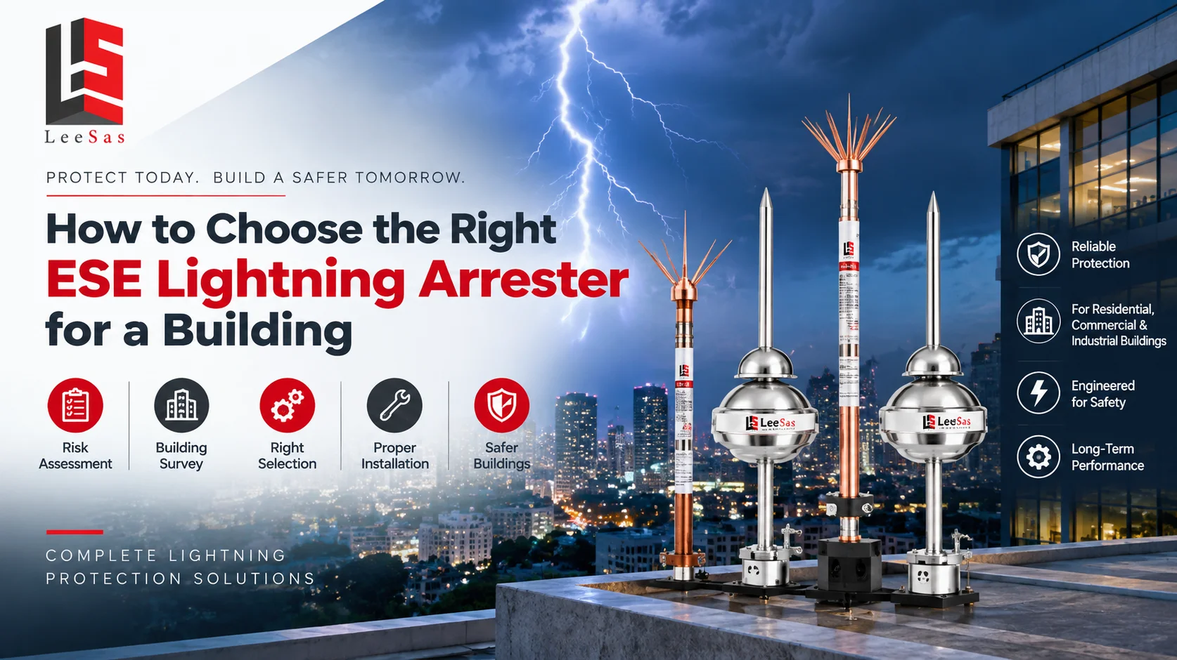
Choose an ESE lightning arrester only after a lightning-risk assessment and complete protection design establish the building’s exposure, dimensions, required protection level, air-terminal location, down-conductor routes, earthing and surge-protection interfaces. The arrester is one component of a system; a product with a large advertised radius cannot compensate for poor placement, an incomplete current path or inadequate bonding.
Leesas Enertech provides a dedicated lightning arrester range and describes assessment, design, supply, installation and maintenance services. Buyers should request the current product certificate, test documentation, model-specific protection data and installation instructions. Local authority, insurer, client and project requirements determine whether a particular ESE method is acceptable and how it must be designed.
What an ESE system includes
| System element | Function | Selection check |
|---|---|---|
| ESE air terminal | Intended interception point | Model data, placement, test evidence and environmental suitability |
| Mast and supports | Positions the terminal above protected features | Height, wind, corrosion, access and structural attachment |
| Down conductors | Carry lightning current toward earth | Route, quantity, separation, bonding and mechanical protection |
| Test joints and earth termination | Enable dissipation and inspection | Electrode design, soil data, access and documented testing |
| Surge protective devices | Limit conducted transient overvoltage | System type, location, coordination and backup protection |
| Bonding and separation measures | Reduce dangerous potential differences and side-flash risk | Metal services, cable routes and equipotential plan |
External lightning protection and internal surge protection address related but different paths. The external system intercepts and conducts lightning current; coordinated surge protective devices help limit transients entering electrical and electronic systems. Leesas lists surge protection devices alongside its external-protection products. Both need to be included in one design with earthing and bonding.
Eight steps for selecting an ESE arrester
1. Complete a project-specific risk assessment
The assessment considers building use, dimensions, location, occupancy, services, contents, consequence of failure and local lightning environment under the applicable method. A warehouse, hospital, data facility, school and isolated residential building do not present the same consequence or continuity needs. The output should state whether protection is required and the protection objective, rather than beginning with a preferred product model.
2. Survey the complete building and surroundings
Record plan dimensions, height, roof levels, parapets, tanks, antennas, solar arrays, HVAC equipment, skylights and nearby taller objects. Identify flammable zones, public access, maintenance routes and incoming metallic and electrical services. Photographs and roof drawings help, but a site survey is important where drawings are outdated. Future rooftop equipment should also be considered because it can change exposure and separation.
3. Establish the protection level and design method
The responsible designer applies the project-approved standard and selects the protection level from the risk assessment. The method defines how a protection volume is calculated and how the ESE terminal’s verified characteristic is used. Do not compare two products using radius figures taken at different heights or protection levels. Ask suppliers to show the assumptions behind every coverage claim.
4. Select a model using verified documentation
Review the exact model designation, manufacturer, material, dimensions, claimed advance time or equivalent characteristic, test basis, certificate issuer, issue date and installation limits. Confirm that certificate and test references match the offered model, not merely the brand. A brochure, web graphic or “tested” statement without traceable documents is insufficient for a safety-critical procurement decision.
5. Position terminals from real roof geometry
Locate the terminal so the calculated protection volume covers all required points at their actual elevations. Roof corners, raised plant, solar panels and architectural features may fall outside a simplified circle drawn on a plan. Several terminals may be necessary for a long, stepped or complex building. Placement must also support safe access and structural mounting without creating a maintenance hazard.
6. Design down-conductor paths
A direct, continuous route reduces unnecessary bends and inductive effects. The number and arrangement of conductors follow the chosen design method and project requirements. Avoid routing close to sensitive cables, combustible materials or regularly occupied access where risk cannot be controlled. Fixings, joints and mechanical protection must suit wind, corrosion, temperature and possible accidental damage.
7. Coordinate the earth-termination and bonding system
The earth termination disperses current, but performance depends on soil, electrodes, connections and the broader earthing network. Review soil information, electrode arrangement, corrosion compatibility, inspection access and test points. Bonding or separation measures manage potential differences and side-flash risk. The protection design should show connections to other earthing systems and incoming metallic services rather than leaving site teams to improvise.
8. Add coordinated surge protection
Direct or nearby lightning can introduce surges through power, data, telecom, security and control circuits. Select surge protective devices for the system configuration, exposure, withstand of downstream equipment and expected current path. Coordinate stages where necessary and keep connecting conductors short and appropriately routed. A rooftop terminal alone does not protect electronics from every conducted transient.
Compare ESE proposals with one compliance table
| Proposal item | Evidence to request | Risk if unclear |
|---|---|---|
| Design basis | Risk assessment, standard, level and drawings | Coverage claim cannot be reviewed |
| Air terminal | Exact model, current certificate and tests | Product identity or performance is uncertain |
| Installation | Mast, supports, conductor, fixings and routes | Scope gaps and unsafe site improvisation |
| Earthing and bonding | Electrodes, joints, test points and integration | Incomplete current path or side-flash risk |
| SPD coordination | Device types, locations and connection details | Sensitive systems remain exposed |
| Handover | As-builts, tests, inspection and maintenance plan | Future verification becomes difficult |
Normalize the quotations before comparing price. One proposal may include only an air terminal and mast, while another includes risk assessment, conductors, earthing, bonding, surge protection, structural support, installation, testing and documentation. List inclusions, exclusions and quantities line by line. A low equipment price can become an expensive project if civil work, access equipment and earthing are omitted.
Building-specific considerations
Industrial facilities
Industrial sites may have stacks, tanks, conveyors, hazardous materials, explosive atmospheres, process controls and wide roof areas. Lightning consequences can include fire, equipment damage and production interruption. Protection design must coordinate with hazardous-area classification, process earthing, structural steel and surge protection. An air terminal should not be positioned or serviced without considering emissions and operating restrictions.
Commercial and residential buildings
Complex roof architecture, terraces, solar arrays, water tanks, antennas and public access influence terminal location and down-conductor routes. Concealed conductors may improve appearance but complicate inspection and separation. The designer should coordinate with architects early. A late installation that crosses façades, waterproofing and finished interiors can create avoidable cost and damage.
Critical and data-dependent facilities
Hospitals, data centres, telecom sites and control facilities need attention to continuity, redundant services, sensitive systems and electromagnetic effects. Coordinated SPDs, bonding, cable routing and maintenance are as important as interception. The protection strategy should align with business-continuity and emergency-power arrangements, and acceptance testing should include the interfaces that the client depends on.
Installation quality checklist
- Air terminal, mast, conductors and accessories match the approved model and drawings.
- Structural supports and waterproofing details are approved for the roof.
- Conductor routes, bends, joints and fixings follow the installation design.
- Separation and bonding decisions are implemented at identified metalwork and services.
- Earth electrodes, test joints and inspection chambers remain accessible.
- SPDs are installed at specified interfaces with suitable backup protection and short connections.
- Continuity and earth tests use the approved method and calibrated instruments.
- As-built drawings, certificates, photographs and baseline results are handed over.
Testing, inspection and maintenance
Inspect after installation, at the planned interval and after events or changes that may affect the system. Check air terminal condition, mast, supports, corrosion, conductors, joints, bonding, test links, earth pits, labels and SPDs. Roof work, new solar panels or antennas can alter the protection volume or damage a conductor. Visual inspection should be supported by continuity and earthing tests appropriate to the design.
Maintain a baseline with instrument details, weather or soil conditions, test configuration and results. Trend changes rather than treating one value as permanent. Surge devices may provide status indication and require replacement after degradation. Leesas describes its background and service coverage on its About Us page the maintenance contract should still identify exact inspection tasks, response and exclusions.
Protection-radius claims: what buyers should verify
A protection radius is not a fixed property that applies at every building. It is derived using a stated method, protection level, terminal characteristic and height relationship. The reference plane and the elevation of the point being protected matter. A brochure may show several radii for one model, each linked to different assumptions. Procurement should request the calculation table and annotated section drawing that show exactly which value was used for the project.
Plan-view circles alone can be misleading on stepped roofs. A lower roof may be covered while a tall rooftop unit projects outside the calculated volume, or a parapet corner may sit at a different elevation from the assumed plane. Review both plan and section views. If several terminals are proposed, show how their volumes address the complete geometry without leaving gaps or introducing conflicting conductor routes.
Mast and structural support are part of the safety design
The air terminal and mast experience wind, self-weight and installation loads. A structural professional should verify mast height, section, base plate, anchors, guying where used and the capacity of the supporting roof or wall. Avoid attaching the mast to non-structural sheets or parapets without verification. Penetrations need approved waterproofing, and dissimilar metals may need corrosion review. The lightning-protection installer and structural or roofing contractor should coordinate one buildable detail.
Access matters throughout the life of the system. Locate the mast so technicians can inspect connections without unsafe climbing or stepping on fragile roofs. Provide fall-protection arrangements and maintain clear space around testable parts. If the roof is likely to receive future solar modules or HVAC equipment, reserve access and document the protected volume so later contractors can request a design review before changing it.
Commissioning and acceptance evidence
Commissioning should verify installed components against the approved bill of materials, confirm conductor continuity and bonding, inspect joints and supports, and test the earth-termination system using the agreed method. Check SPD status, backup protection and connection routing where included. Photographs should identify concealed work before closure. Any deviation from the design needs documented engineering disposition rather than an informal site approval.
The final package should contain the risk assessment, calculations, approved drawings, product and test documentation, material records, installation inspection, baseline test results, as-built drawings and maintenance schedule. Building owners also need a change-control note explaining that roof additions, façade work, new services or earthing alterations can require reassessment. Acceptance is complete when the future inspector can understand what was installed and why.
Common selection mistakes
Common mistakes include selecting by the largest radius in a brochure, skipping the risk assessment, ignoring raised roof equipment, using a certificate from a different model, providing one down conductor where the design requires more, omitting bonding, treating earthing as a fixed resistance promise and forgetting surge protection. Another error is assuming an ESE product makes a whole building compliant by itself.
After handover, appoint an owner for the records and inspection calendar. Without clear responsibility, roof alterations and expired maintenance actions can silently undermine an otherwise sound installation.
Avoid claims that any system can guarantee zero lightning damage. Protection reduces managed risk when correctly designed, installed and maintained. Weather, building changes, service condition and documentation all influence long-term performance. Independent project review is appropriate where safety, critical operations or regulatory acceptance demand it.
Frequently Asked Questions
1. What does ESE mean in lightning protection?
ESE refers to Early Streamer Emission. Its use, design method and acceptance must follow the project-approved requirements and verified product documentation. Lightning-protection selection and design require a competent professional, verified site data, certified product documentation and the standards and approvals applicable to the project.
2. Can I select an ESE arrester by building height alone?
No. Plan dimensions, roof levels, exposure, use, risk, protection level, surroundings and system design also matter. Lightning-protection selection and design require a competent professional, verified site data, certified product documentation and the standards and approvals applicable to the project.
3. Is a larger advertised protection radius always better?
No. Radius depends on stated design assumptions such as protection level and terminal height. Compare products only on the same approved basis. Lightning-protection selection and design require a competent professional, verified site data, certified product documentation and the standards and approvals applicable to the project.
4. How many ESE terminals does a building need?
The design determines quantity from the required protection volume and real building geometry. Complex or long structures may require more than one. Lightning-protection selection and design require a competent professional, verified site data, certified product documentation and the standards and approvals applicable to the project.
5. Does an ESE terminal need down conductors?
Yes. Intercepted current requires approved conductive paths to the earth-termination system, with routing and fixing designed for lightning current. Lightning-protection selection and design require a competent professional, verified site data, certified product documentation and the standards and approvals applicable to the project.
6. Does an ESE system replace surge protection devices?
No. SPDs help limit conducted transients on power and signal systems and are coordinated with the external lightning-protection and bonding design. Lightning-protection selection and design require a competent professional, verified site data, certified product documentation and the standards and approvals applicable to the project.
7. What documents should a supplier provide?
Request exact model datasheets, certificates and tests, design calculations, drawings, materials, installation method, test reports, as-builts and maintenance guidance. Lightning-protection selection and design require a competent professional, verified site data, certified product documentation and the standards and approvals applicable to the project.
8. Can one earth pit serve the complete system?
Electrode quantity and integration depend on the design, soil and applicable method. A generic one-pit rule is not suitable for every building. Lightning-protection selection and design require a competent professional, verified site data, certified product documentation and the standards and approvals applicable to the project.
9. Where should the air terminal be installed?
At the approved position and height that provides the calculated coverage while allowing structurally sound support, safe access and correct conductor routing. Lightning-protection selection and design require a competent professional, verified site data, certified product documentation and the standards and approvals applicable to the project.
10. How often should the system be inspected?
Follow the risk-based maintenance plan, applicable requirements and manufacturer guidance, with additional checks after suspected events or building modifications. Lightning-protection selection and design require a competent professional, verified site data, certified product documentation and the standards and approvals applicable to the project.
11. What site information is needed for a proposal?
Provide location, building drawings, heights, roof plan, services, use, existing earthing, sensitive equipment, project criteria and available risk assessment. Lightning-protection selection and design require a competent professional, verified site data, certified product documentation and the standards and approvals applicable to the project.
12. Can ESE protection guarantee that lightning will never cause damage?
No system can offer an absolute guarantee. A complete, maintained design reduces risk and manages lightning-current paths and transient effects. Lightning-protection selection and design require a competent professional, verified site data, certified product documentation and the standards and approvals applicable to the project.
Build a Verifiable Lightning-Protection Path from Roof to Earth
The right ESE lightning arrester is selected within a documented system that connects risk assessment, verified product data, real roof geometry, down conductors, bonding, earthing and surge protection. Leesas Enertech can review building drawings, protection objectives and available site data before defining a technical scope. Share your project details through the Leesas Enertech contact page to request a design-aligned proposal.


