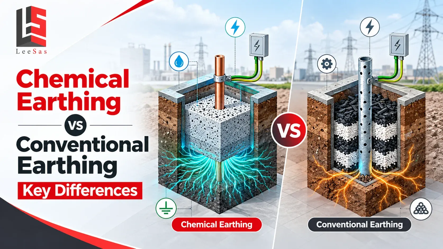
The choice between chemical earthing and conventional earthing should not begin with a product name. It should begin with soil resistivity, the electrical system, expected fault current, permissible touch and step voltage, available installation area, corrosion conditions and the maintenance capability of the site. Either method can perform poorly when it is selected from a generic specification and installed without testing.
In simple terms, a chemical earthing system uses an electrode surrounded by a purpose-designed conductive backfill or earthing enhancing compound. Conventional earthing uses a rod, pipe, plate, strip or grid installed in the ground, often relying mainly on the native soil and a traditional construction method. The word chemical does not automatically mean hazardous, maintenance-free or superior. The composition, test evidence and compatibility of the backfill matter.
For commercial and industrial buyers, the practical conclusion is clear: chemical earthing is often useful where soil resistivity is high or seasonal performance is difficult to stabilize. Conventional earthing can remain effective and economical where soil conditions, electrode geometry and available space support the required result. The final decision must be based on engineered calculations and field measurements, not a fixed resistance promise.
What is earthing and why does it matter
Earthing, also called grounding in many international references, connects selected conductive parts of an electrical installation to the general mass of earth through a designed electrode system. It gives fault and lightning current an intended path, supports protective-device operation, limits dangerous voltage differences and helps stabilize system voltage under defined conditions.
A complete earthing arrangement may include equipment protective conductors, earth continuity conductors, electrodes, buried grids or rings, inspection chambers, test links, bonding conductors and connections to the main earthing terminal. Lightning protection, power-system earthing, electronic reference grounding and static control can have related but different performance requirements. They must be coordinated rather than treated as one isolated earth pit.
What is a chemical earthing system
Chemical earthing is a market term for an earthing arrangement in which an electrode is installed with a conductive, moisture-managing or low-resistivity backfill. The compound increases the effective contact between the electrode and surrounding ground and can reduce local resistance where native soil is dry, rocky, sandy or otherwise resistive. Common systems use GI, copper, copper-bonded or other specified electrodes with an engineered earthing compound.
The backfill should be selected from documented electrical, chemical, corrosion and environmental properties. IEC 62561-7 covers requirements and tests for earthing enhancing compounds used as lightning protection system components. A responsible specification asks for the product data, resistivity test method, installation instructions, stability, corrosion behaviour and conformity evidence rather than accepting any black powder described as a chemical.
Chemical earthing does not create a permanently constant value. Soil moisture, temperature, electrode depth, compound condition, joints, nearby construction and seasonal groundwater changes can still affect readings. The system needs accessible test points and a documented inspection plan.
What is conventional earthing
Conventional earthing uses established electrode forms such as driven rods, GI pipes, copper pipes, plates, strips, rings or buried grids. The electrode exchanges current with the surrounding soil through its surface area and the geometry of the complete system. More than one electrode may be connected to achieve the required resistance, current distribution and safety performance.
Some traditional installations use charcoal and salt around an electrode. That practice should not be treated as the definition of every conventional system or automatically copied into a new design. Salt can increase soil conductivity temporarily, but it can also accelerate corrosion, wash away and change soil chemistry. A modern conventional system may use properly selected rods or a grid in native soil without routine salt and water dosing.
Conventional systems are familiar, easy to inspect and can be cost-effective in suitable soil. Their performance depends heavily on electrode material, dimensions, depth, spacing, soil resistivity, moisture and connection quality. Where land is available, extending the grid or adding properly spaced electrodes may provide a more durable answer than repeatedly treating one small pit.
Chemical earthing vs conventional earthing at a glance
| Factor | Chemical earthing | Conventional earthing |
|---|---|---|
| Basic method | Electrode plus engineered conductive backfill | Rod, pipe, plate, strip or grid relying mainly on soil and geometry |
| Best fit | High or variable soil resistivity and restricted installation area | Suitable soil, adequate space and straightforward grounding duties |
| Initial cost | Usually higher per pit because of electrode and compound | Often lower for a simple electrode, but grids or many rods can cost more |
| Resistance stability | Can improve local soil contact and seasonal consistency | Depends more directly on native soil moisture and resistivity |
| Maintenance | Inspection and testing remain necessary; replenishment depends on design | Testing, joint inspection and possible corrective extension are required |
| Corrosion risk | Depends on electrode and compound compatibility | Depends on soil, electrode material and any traditional additives |
| Design flexibility | Useful when deep driving or large grids are difficult | Many electrode geometries can be engineered for the site |
| Verification | Test the installed system and review compound documents | Test the installed system and verify electrode layout and continuity |
How both systems carry fault current into the ground
Electrical current does not disappear at the earth pit. It spreads from the electrode into the surrounding soil. Resistance is influenced by the electrode-to-soil interface and by progressively larger volumes of earth around the electrode. This is why simply increasing electrode diameter produces limited benefit compared with changes in depth, number, spacing or grid geometry.
A chemical backfill reduces resistivity close to the electrode and improves physical contact, which can lower the local component of resistance. A conventional design reaches the target through suitable electrode material, depth, spacing and total buried area. In both cases, conductors and joints must safely withstand the expected current and thermal stress, while the overall design controls touch and step potentials where people may be exposed.
Which system provides lower earth resistance
Chemical earthing may achieve a lower measured resistance than one basic conventional electrode in difficult soil, but that is not a universal comparison. A well-designed conventional grid with several spaced electrodes can outperform a poorly installed chemical pit. Results must be compared on the same site, with equivalent electrode depth, material, spacing and test conditions.
No single earth-resistance value suits every project. The required value and safety criteria depend on the supply arrangement, fault-clearing protection, voltage level, installation type, lightning protection design, utility requirements and governing standard. Substations also require step-and-touch voltage analysis; a low resistance reading alone does not prove that a grid is safe.
Buyers should ask the contractor to state the design target, calculation method, soil-resistivity data, test method and corrective plan if commissioning results are outside the accepted range. An unexplained guarantee such as maintenance-free one ohm earthing should be treated cautiously.
Cost comparison and lifecycle value
Conventional earthing often has a lower entry cost when one or two standard rods or pipes can meet the requirement. Chemical earthing adds the cost of a purpose-designed electrode, backfill and controlled installation. However, purchase price per pit is not a fair lifecycle comparison.
In rocky or high-resistivity ground, a conventional solution may require deeper drilling, more electrodes, longer conductors, a larger grid and additional civil work. Chemical backfill may reduce that footprint. On the other hand, poor-quality compound, incompatible materials or an inaccessible proprietary electrode can create future replacement costs. Compare design, excavation, materials, testing, documentation, corrective work and maintenance over the intended service life.
Performance in different soil conditions
Moist clay generally has lower resistivity than dry sand, gravel or rock, but broad soil labels are not enough for design. A site can contain conductive topsoil over a resistive layer, seasonal groundwater, filled ground or chemically aggressive zones. Measurements at different probe spacings help show whether deeper electrodes, horizontal conductors or a local enhancing compound will be effective. The same electrode can produce very different results only a few metres away.
In dry or sandy soil, a chemical earthing system can improve the immediate electrode environment and reduce dependence on short-term surface moisture. It cannot create unlimited conductive volume, however. If the resistive formation extends far beyond the treated zone, the design may still need greater depth, multiple electrodes or a buried ring. In waterlogged or saline ground, the priority may shift toward corrosion-resistant materials and reliable connections rather than adding more conductive material.
Rocky sites require particular care because a narrow drilled hole can restrict current dispersal. Conductive backfill can improve contact within the bore, while a network of drilled electrodes or horizontal conductors may be needed to reach the safety target. On campuses and large industrial plots, a conventional mesh or ring can use the available area and equalize potential more effectively than concentrating the entire design at one enhanced pit. Soil data therefore determines not only resistance but also the most useful geometry.
Environmental and installation quality considerations
The environmental question is not answered by labels such as chemical or natural. Review safety information, leaching behaviour, pH, stability and disposal guidance for the compound. Control the specified quantity, mixing, bore dimensions and installation steps because substitutions can change electrical performance and corrosion behaviour.
Maintenance durability and corrosion
Neither method should be sold as maintenance-free. Visual inspection should cover chambers, labels, test links, conductor damage, loose or overheated connections, waterlogging and visible corrosion. Electrical tests should be recorded against the commissioning baseline so gradual deterioration can be identified.
Electrode life depends on material thickness, coating quality, soil chemistry, moisture, stray current and galvanic interaction with connected metals. Copper-bonded rods combine a steel core with a bonded copper layer, while galvanized electrodes use zinc protection. The correct option depends on site chemistry and connected materials. Mixing incompatible metals or using aggressive additives can shorten life even when the initial test result looks good.
An earthing enhancing compound should remain stable and should not create unacceptable corrosion or environmental leaching. Request model-specific test evidence and follow the manufacturer’s quantity, mixing and installation instructions. Adding water or salt without a documented design may improve a reading briefly while hiding the real cause of poor performance.
How to choose the right earthing method
Measure soil resistivity
Use a suitable field method, commonly the Wenner four-point method, at relevant spacings and locations. One surface observation cannot represent layered or seasonally changing soil.
Define the electrical duty
Identify system voltage, fault current, protection clearing time, lightning duty, sensitive loads and applicable touch-and-step criteria. A residential installation and an industrial substation do not need the same design process.
Study space and construction limits
Check drilling access, underground services, foundations, pipelines, future expansion, flooding, rock depth and the area available for electrode spacing or a grid.
Compare complete proposals
Ask for electrode material and dimensions, conductor size, backfill data, pit details, number and spacing of electrodes, connection method, test points, commissioning criteria and exclusions.
Plan verification and maintenance
The design should state how resistance or impedance, continuity and connections will be checked, who owns the records and what action follows a failed result.
Application based selection guide
| Site or duty | Practical approach |
|---|---|
| Typical industrial plant | Select after soil testing; combine electrodes into a coordinated plant network |
| Rocky or dry site | Chemical backfill or engineered deep electrodes may reduce the required footprint |
| Substation | Use a calculated grid with step-and-touch analysis; compounds may support specific electrodes |
| Lightning protection | Coordinate earth termination, bonding and SPDs under the chosen lightning standard |
| Telecom or sensitive electronics | Control bonding and surge paths; do not create isolated earths without engineering review |
| Existing high-resistance pit | Diagnose joints, corrosion, soil and layout before adding compound or another electrode |
Standards testing and commissioning
For Indian projects, IS 3043 is a key reference for earthing practice, while the project may also invoke electricity regulations, utility rules, IEC requirements, consultant specifications or sector standards. IEC 60364-5-54 addresses earthing arrangements and protective conductors in low-voltage installations. For lightning protection components, the IEC 62561 series includes requirements for conductors, earth electrodes and earthing enhancing compounds. Substation projects may also use a recognized grid-design standard such as IEEE 80 where specified.
Commissioning should verify installation against approved drawings, conductor continuity, connection quality, electrode identification and test results. The fall-of-potential method is widely used for earth resistance where probe spacing and site conditions allow. Clamp testing can be useful on suitable multi-path systems but is not valid for every isolated electrode. Record the instrument, method, lead arrangement, weather, soil condition and disconnected or connected state so later readings are comparable.
Common procurement mistakes
Common mistakes include selecting from electrode length alone, accepting an unverified compound, specifying one resistance value for every facility, placing several rods too close together, mixing metals without compatibility review, hiding test joints below finished surfaces and measuring immediately after artificial watering. Buyers also create risk when separate equipment, lightning and electronic earths are installed without a bonding study.
A credible quotation explains how the system was sized and what happens if the field result differs from the design. It separates supplied products from civil work, testing, documentation and maintenance. That transparency makes chemical earthing vs conventional earthing a technical decision rather than a catalogue comparison.
Frequently asked questions
1. What is the main difference between chemical and conventional earthing?
Chemical earthing uses an engineered conductive backfill around the electrode. Conventional earthing relies mainly on selected electrode geometry and the native soil, although construction details vary.
2. Is chemical earthing always better?
No. It is useful in many high-resistivity or space-restricted sites, but a properly designed conventional rod or grid system can be more suitable and economical in favourable soil.
3. Does chemical earthing require maintenance?
Yes. The chamber, connections, conductor continuity, corrosion condition and electrical performance still require planned inspection and testing. Maintenance frequency should follow the project standard and risk.
4. Is conventional earthing only charcoal and salt earthing?
No. Conventional systems include rods, pipes, plates, rings, strips and grids. Charcoal and salt are traditional additives, not the definition of conventional earthing.
5. Can salt reduce earth resistance?
Salt may lower soil resistivity temporarily, but it can wash away, alter soil chemistry and accelerate corrosion. It should not be added routinely without an approved design.
6. Which system lasts longer?
Service life depends on electrode material, coating, soil chemistry, compound compatibility, installation quality and corrosion exposure. The method name alone cannot predict lifespan.
7. Is chemical earthing more expensive?
Its initial cost per electrode is often higher. Total project cost may still be competitive where conventional earthing would require more excavation, electrodes, conductor length or space.
8. What resistance value should an earth pit achieve?
There is no universal value for every installation. The accepted target depends on the electrical system, fault protection, voltage, lightning duty, utility rules and governing standard.
9. How is soil resistivity measured?
The Wenner four-point method is commonly used. Measurements at several spacings and locations help reveal soil variation and guide electrode depth and grid design.
10. Can chemical earthing work in rocky soil?
It can improve contact around a drilled electrode, but rock depth, available bore size, moisture and surrounding geology still matter. Site-specific design and testing are necessary.
11. What materials are used for earthing electrodes?
Common options include galvanized steel, copper, copper-bonded steel and stainless steel for particular environments. Selection depends on conductivity, strength, corrosion and compatibility.
12. Can one earth pit protect an entire factory?
A factory normally needs a coordinated earthing network designed for its distribution system, equipment, buildings and lightning protection. One isolated pit is rarely an adequate planning basis.
13. How often should earthing be tested?
Follow the applicable regulations, standard, site risk and maintenance plan. Test after major electrical changes, excavation near electrodes, lightning events or evidence of connection damage.
14. What documents should a supplier provide?
Request the design basis, soil data, electrode and compound specifications, conformity evidence, layout, connection method, test procedure, commissioning report, as-built drawing and maintenance plan.
15. Which earthing system is best for an industrial project?
The best system is the one engineered for measured soil conditions, fault duty, safety criteria, space, corrosion exposure and lifecycle support. It may use conventional electrodes, enhancing compound or both.
Choose an earthing system based on site data with Leesas Enertech
Chemical earthing and conventional earthing can both support safe, reliable grounding when the system is designed around real soil and electrical conditions. Leesas Enertech LLP provides earthing and grounding support covering site assessment, product selection, electrodes, earthing compounds, installation guidance, testing, maintenance and AMC or CAMC requirements. Through its partnership with Topbas, Turkey, Leesas supplies options including GI pipe electrodes, copper and copper-bonded earth rods, earthing enhancing compounds, inspection components and associated grounding products. Share your soil information, single-line diagram, fault details, site layout and required standard with the Leesas team to receive a technically reviewed recommendation and quotation built around measurable performance rather than a one-size-fits-all earth pit.


